
SIVACON 8PS TRUNKING SYSTEMS
LDM-P system

Cost-efficient and safe link between transformers and inverters in photovoltaic stations
Sustainable power distribution in solar applications
Photovoltaic stations (PV stations) are characterised by a high power volume in the smallest space. Furthermore, such stations must ensure a high availability and operational safety while at the same time keeping maintenance requirements as low as possible. And, not the least, the corre- sponding modules shall be produced in large quantities in a standardised way optimised for production. Especially for high currents, busbar trunking systems have prevailed as an efficient, safe, and standard-compliant alternative to classical cables in many areas of application.
With the LDM-P system, Siemens now also opens up the characteristic potentials of this technology for photovoltaic stations.
Equally, the use for further container solutions is possible, in which the busbar trunking system is mounted in a protected way.
Proven solution, further developed
The LDM system – originally designed for wind turbines – was developed further
for specific applications. One innovation of the LDM-P versions lies in the fact that this system, which was conceived for use in closed stations, works without housings.
It is designed for current ratings up to 7,000 A.
As the connections between the busbar and the transformer on one side or the converter on the other side are not standardised, every LDM-P application is a customer- specific solution.
Advantages for efficient use
Three advantages predestine busbar trunking systems for use in photovoltaic stations: efficient power transmission at high currents, low fire load, and the high safety standards of a design verified low-voltage switchgear and controlgear assembly in accordance with IEC 61439. In addition, material costs for aluminium are below those for copper cables. The LDM-P busbar trunking system now offers a corresponding solution especially for OEMs in the solar industry.

Connection piece, on the transformer side

Straight length between inverter and transformer
System
LDM-P13 LDM-P14. LDM-P16 LDM-P24. LDM-P36
Regulations and standards
IEC/EN 61439-1/-6
Rated operational voltage Ue
1,000 V
Rated current Inc. [A] @35°
PE conductor
no


Degree of protection
Housing
Short-circuit rating
Rated short-time withstand
current 0.1 s. Icw
Ipk
Ambient temperature
Cross-section per phase [mm2]
Weight [kg/m]
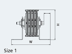
Dimensions (incl. supports). [mm] W
D
Drawing (schematic sketch)
@50°
1800 2500 2900 4200 7000
1600 2300 2700 3900 6600
IP00
Without housing (protection of persons must be
ensured by measures on site)
105 kA
50 kA
min. -5° C/max. 45° C
698 1014 1203 2028 3609
~8.5 ~11.5 ~13 ~20 ~33
244 301 358
191
Size 1 Size 2 Size 3
Technical data
Busbar coating | Epoxy | 19 |
Your benefit
-
Modular system for individual customer requirements
-
Pre-defined impedances and stipulated technical features
-
Efficient installation
-
Compact, maintenance-free
-
busbar trunking systems